

Building an adjustable mortising jig for your plunge router essentially creates a benchtop joinery tool. Over the years, I gravitated to power tool joinery methods: biscuits, dowels, loose tenons. They click for the way I work.
ShopNotes has featured several different jigs — I even wrote about some of them. They range from simple to complex. When it came time to make a version for myself, the jumping off point took the form of the two jigs shown. To be clear, there isn’t anything wrong with how they work. They are easy to set up, accurate, and straightforward to create.
 |
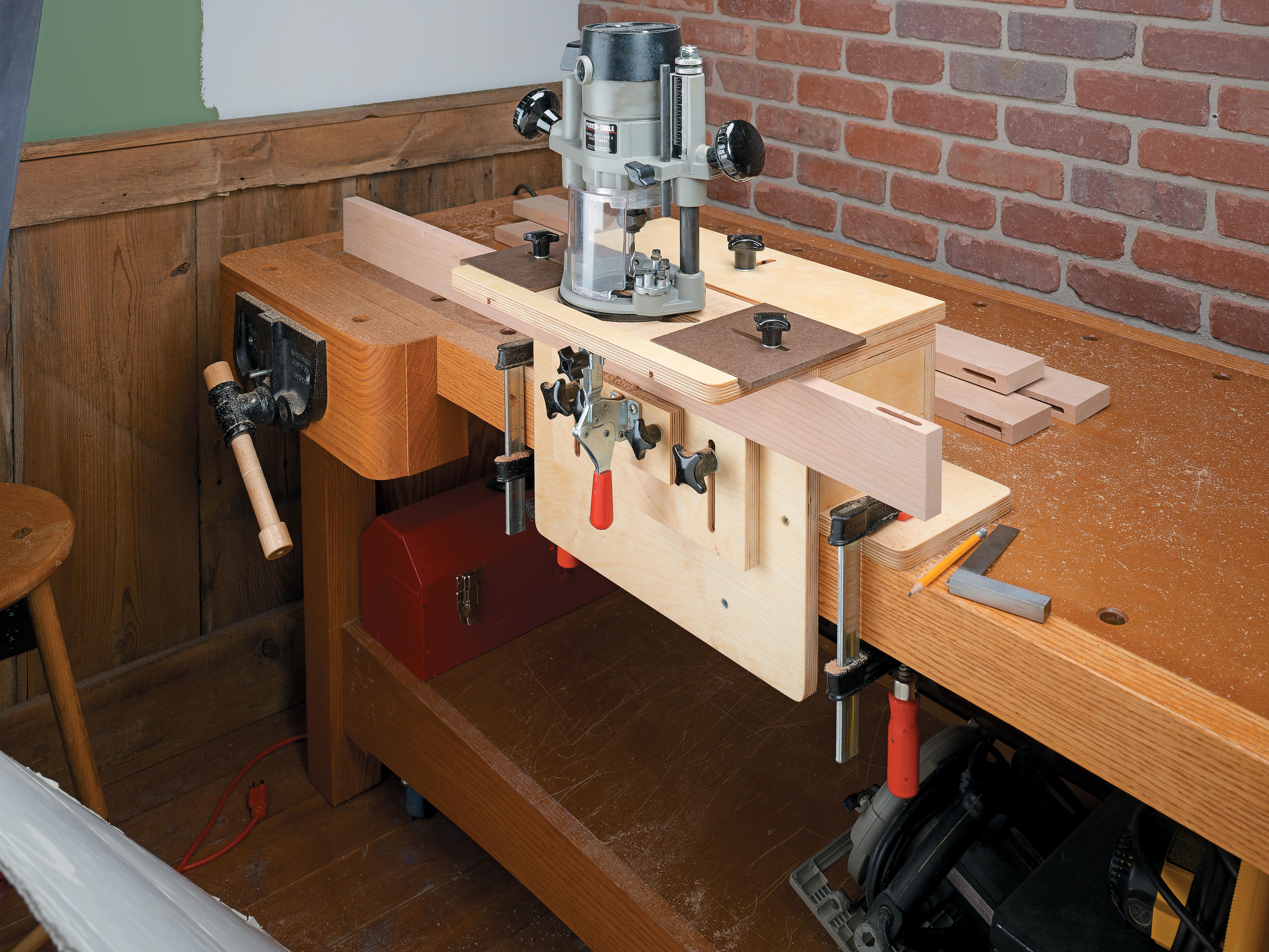 |
| An early ShopNotes mortising jig from issue 64. The front block can rotate for mortises in all kinds of parts. | This jig (issue 112) offers some upgrades to the earlier model. It’s the basis for the jig I made ... and modified. |
As I worked with my first iteration, a few modifications came to mind. As an aside, I don’t feel like I truly own a tool unless I’ve customized it in some way.
THE LATEST MODEL.
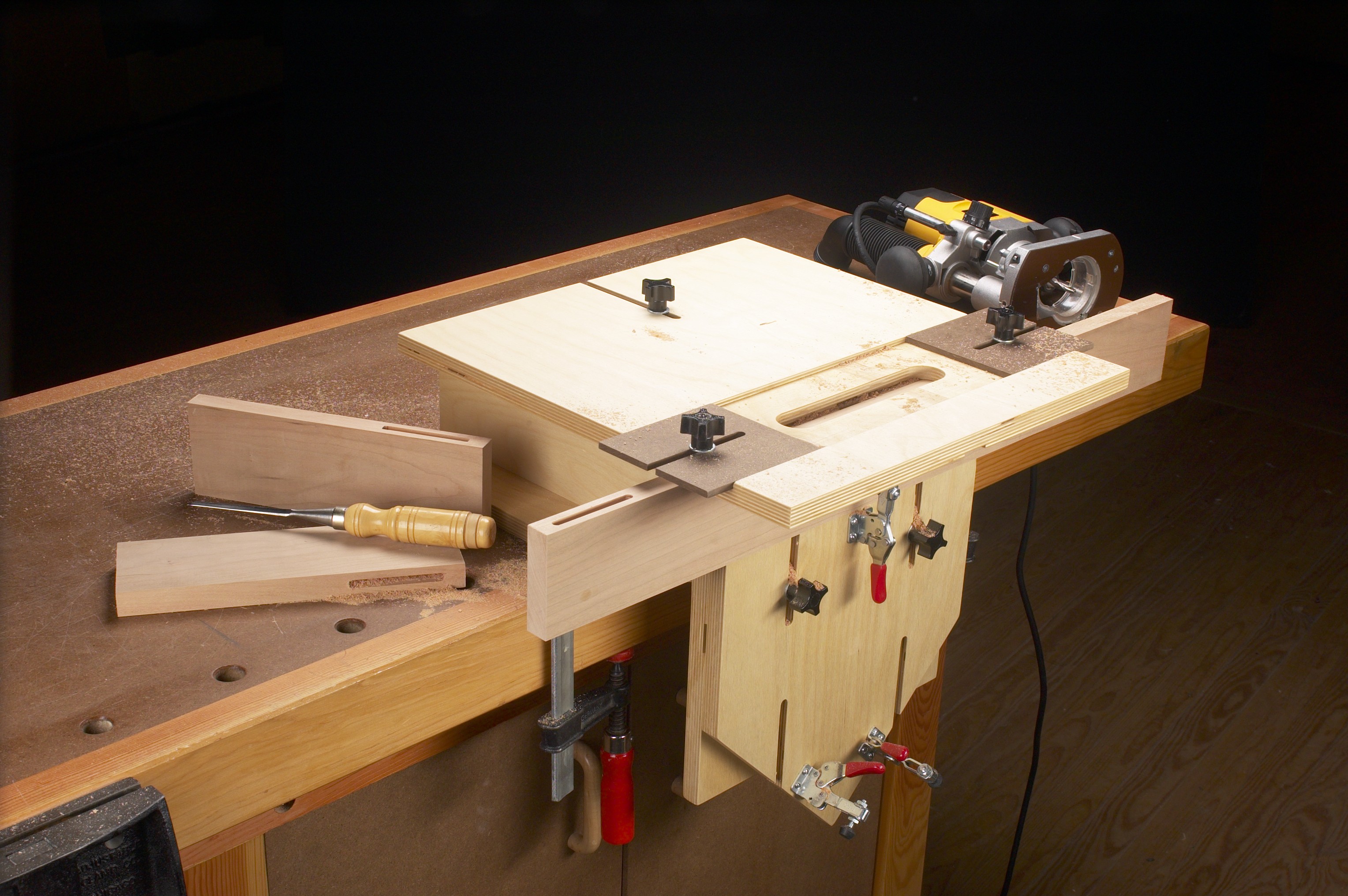
The result is the one shown in the main photo. There are some big differences, but the family resemblance shines through. I’ll walk you through my changes and what each allows me to do.
The goal isn’t to sell you on my upgrades. Instead, I want you to see that the plans in this (or any other form) are a starting point. It’s up to you to make it your own.
First things first. Yes, the back part of the jig is painted. “Persimmon” (if you want to know) from General Finishes’ line of acrylic milk paint. Orange is my favorite color. Design details matter.
VERSATILE TOP
One of my first changes was to redo the top. That change was driven by a change in equipment. As built, the earlier jigs have a channel in the top sized to match the base of the router - it keeps the router on track. So what happens if your router changes? In my case, I wanted to use my small palm router for making smaller mortises. My Porter Cable 690 is reserved for larger tasks.
GUIDANCE.
My solution was to change how the router is guided in the jig. I routed a slot to accept a 1" O.D. guide bushing. This slot is large enough to accept my usual range of bits: 1/4", 8mm, 3/8", and 1/2". There’s also plenty of room for chips to clear. Switching routers is now as easy as installing a guide bushing. If I change tools down the road, the jig will still work just fine.
A few other points to keep in mind. You want the bushing to run smoothly in the slot without any play. I had to sand the edges a bit to get the right motion. Even though the top is made from 1/2" Baltic birch plywood, I didn’t want the slot to wallow out over time.
I sealed the edges with a couple coats of thin CA glue. It soaks into the plywood rather than building up a finish that would alter the fit of the bushing. Finally, I painted the top a light gray and sprayed on some lacquer.
SETTING STOPS.
This change required me to modify the end stops. The stops are hardboard squares with an open slot. You can see these in the photo. The slot slides along runners mortised into the top.
 |
| An accurate, reliable working jig begins with the top. Adjustable stops control the length of the mortise. A precision slot accepts a guide bushing to keep the router moving in a straight line. |
Threaded knobs lock the stops in position. I’m thrifty, so I tapped threads into the plywood (sealed again with CA glue). Threaded inserts or T-nuts would also work, though they may need to modified themselves to work in thinner plywood.
ORIENTATION.
The next change isn’t as noticeable. I marked centerlines in both directions on the inside slot. Again, you can see this best in the closeup below. This is a decision based on simplifying the layout process and avoiding confusion during the construction process.
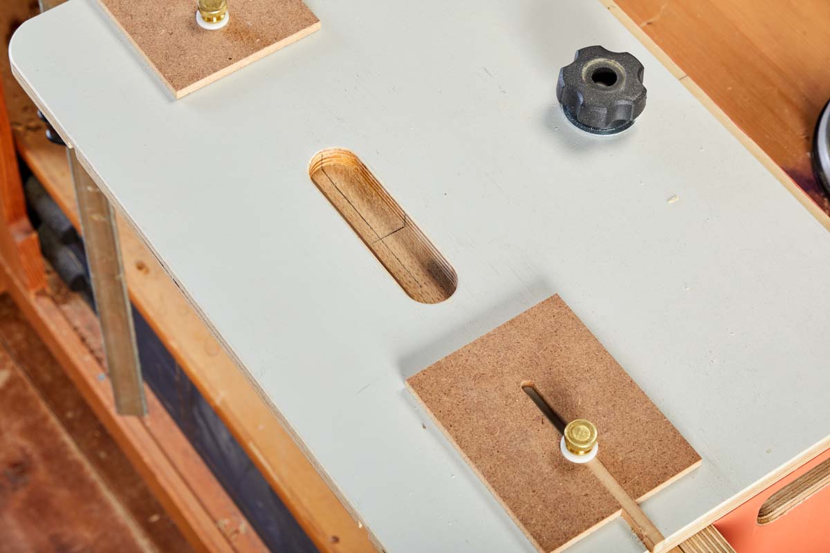 |
| Finely marked centerlines in the slot are used to position the jig’s top, and thus the router bit, in relation to similarly marked lines on the workpiece for accurate work. |
By marking centerlines on one of my workpieces, I can adjust the top of the jig until the lines on the workpiece match up with the lines in the slot. From there the jig is programmed for all the parts that follow. Well, there are a couple of other items that follow from this. We’ll get to those presently.
FACE OFF
After refitting the top of the mortising jig, my attention shifted to the face of the jig. Here again, the stock plans work well. Both jigs use an array of T-nuts to hold various supports. What I wanted was a better method for mortising multiple, identical parts — something that’s pretty common.
In addition, I use loose tenon joinery frequently, so I needed simple solutions for supporting a workpiece held horizontally and for securing a workpiece vertically when routing a mortise into its end.
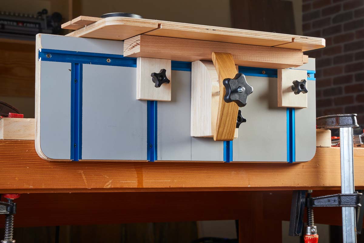
RIGHT ON TRACK.
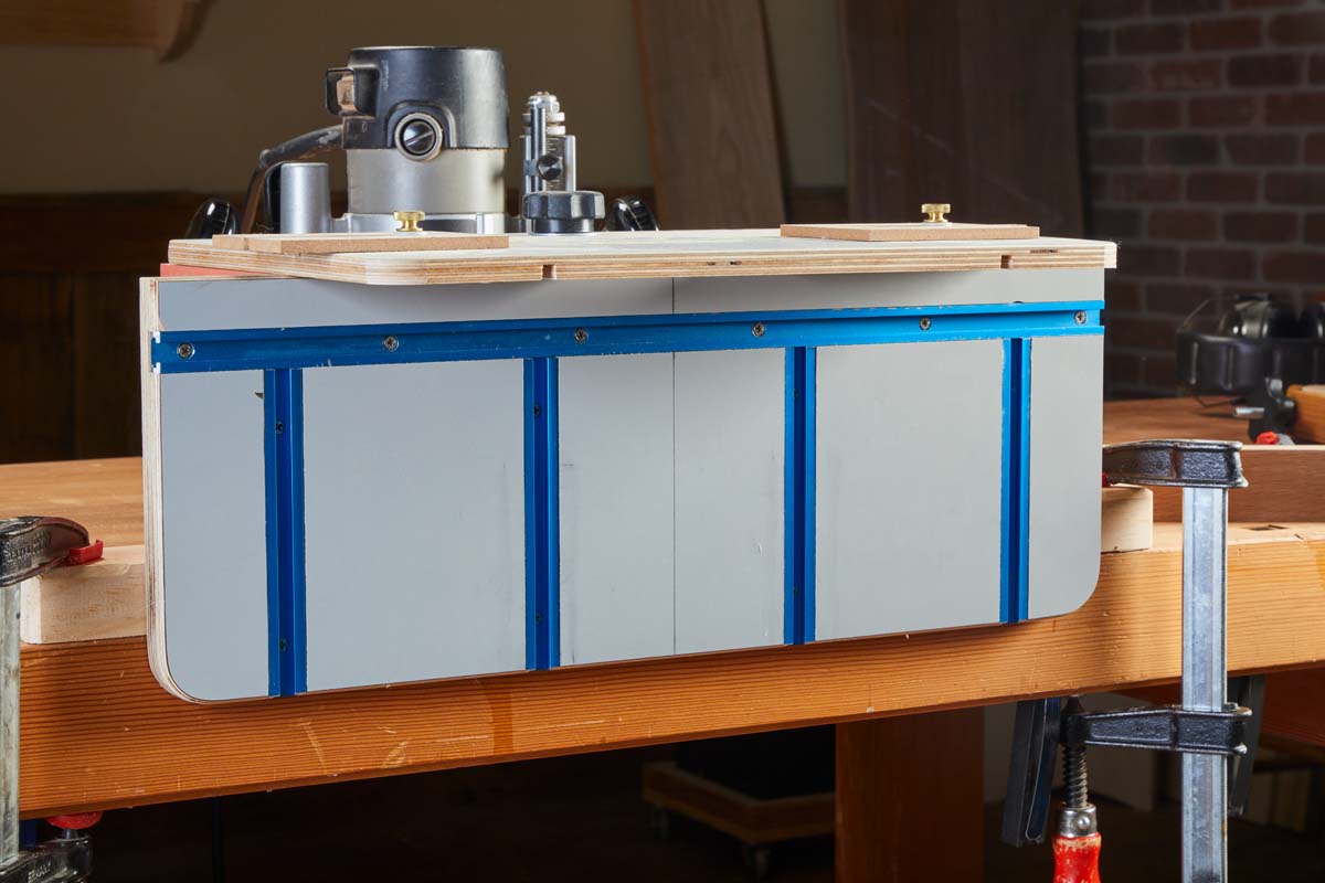 |
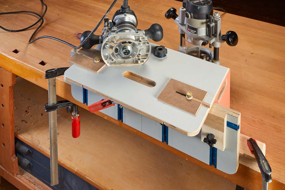
| Covering the face of the jig with plastic laminate creates a durable, smooth surface. T-tracks open up wide accessory possibilities. |
The jig face shown in the photo above is my response to those needs. Actually, I made this for another attempt at a mortising jig. That one didn’t work out, but I liked how this part functioned.
There are two main differences. First, this face is wider than the originals. This provides more support for long parts held horizontally.
The second difference is the use of five runs of aluminum T-track instead of the T-nuts. It may seem like a small detail, but the tracks allow for more accessory options. And it’s all about the accessories, right? One length of track is parallel to the top. The other four tracks run vertically. Feel free to set your own pattern.
T-tracks aren’t the only way to gain flexibility. The box below shows a shop-made solution. One final change is the use of plastic laminate to cover the surface. It’s durable, smooth, and entirely optional.
FIND YOUR CENTER.
Take another look at the new jig face. I marked a centerline here as well. During initial set up, I’m usually crouching down to get the workpiece and stops in place (more on these in a bit). The centerline helps me keep my bearings.
TRACK ACCESSORIES
Here’s how I put the T-tracks to work. Some of these solutions are utility infielders. Others are specialists.
SUPPORTS.
Simple, square pieces of plywood are the first type. These are shown in the photo above. They have a hardboard runner to fit the T-track and prevent spinning. Their main function is to support parts in a horizontal position from below.
On a related note, I use the face of the jig and the underside of the top as my reference surfaces for a workpiece. I tuck the workpiece into the corner and then bring up the supports. A little play in the fit of the supports allows them to sit flat.
END STOP.
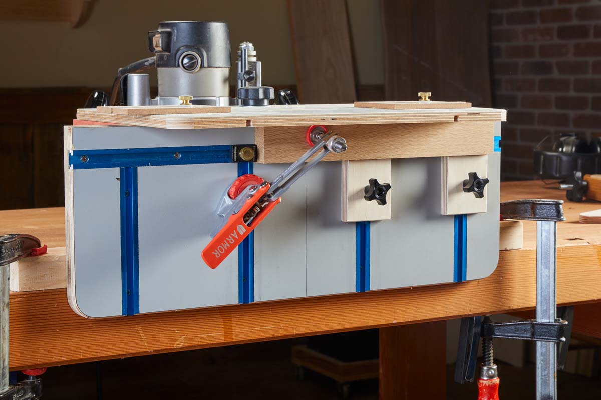 |
| This setup shows my typical mortising arrangement. An end stop registers multiple parts. Two supports below prevent shifting. A toggle clamp locks the piece down snug. |
I had a Woodpeckers track stop in a drawer and found a use for it here. When fixed in the upper track it serves as an end stop, registering parts for production work.
TOGGLE CLAMP.
In order to pin a workpiece in place, I use a self-adjusting toggle clamp by Armor. It has a flange on the bottom that slides in the track without having to mount it to a block. A knob allows you to lock it in place.
Unlike basic toggle clamps, this style provides the same clamping pressure no matter the thickness of the workpiece. I think it works like magic.
VERTICAL SUPPORT.
When routing the end of a workpiece, you need support alongside the part for accurate alignment with the bit. For these operations, I made the block shown in the lower left photo. It runs in the upper track for easy side-to-side adjustment.
Start by registering the workpiece against the underside of the top. Then bring the block up to it in order to keep it square to the bit. Paired with the toggle clamp, that’s all you need for routing a mortise for loose tenon work.
I don’t often use miters. But when I was making the vertical block, I decided to miter the opposite edge. So if needed, I can reinforce the miter with a loose tenon.
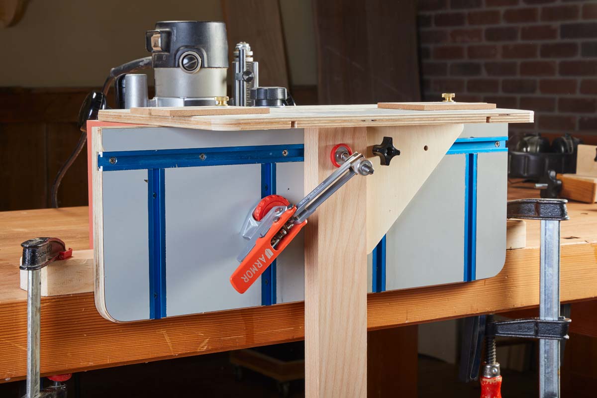 |
 |
| A dual-purpose support is used primarily for routing mortises in the end of a workpiece. An angled face is for mortising miters. |
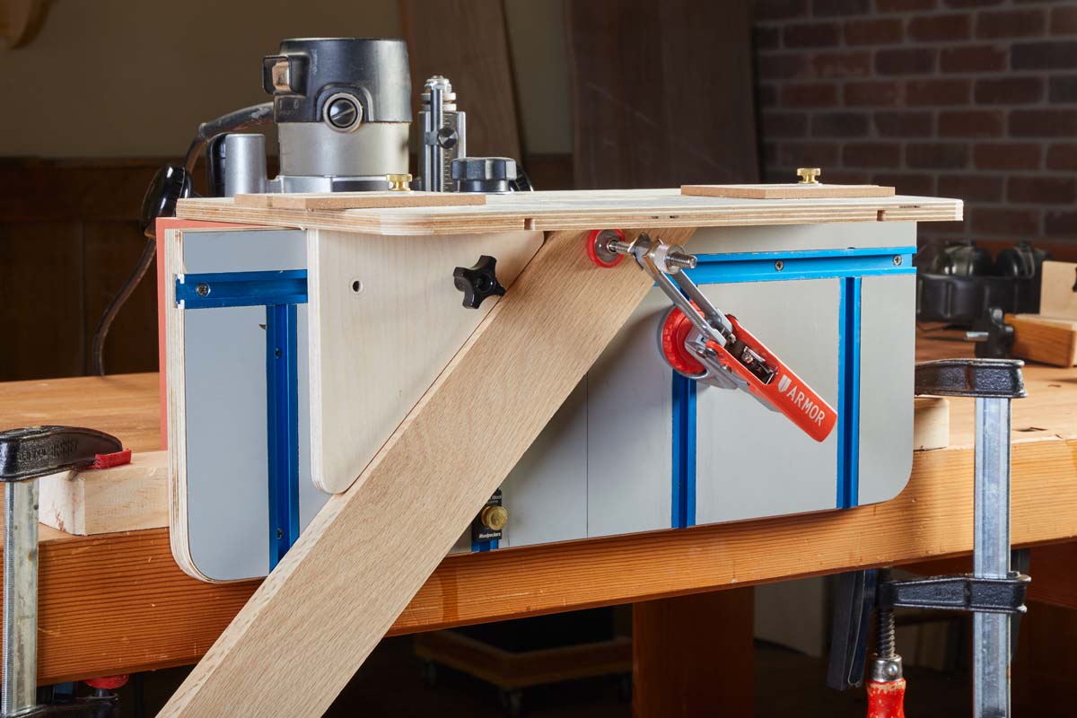
 |
| The custom block shown here clamps wide parts in place for routing mortises in the faces of aprons and stretchers. |
FLAT WORK.
Most mortises are cut into edges and ends of parts. Sometimes though, a mortise needs to be made in the face. Registering and supporting need a different solution. The block below is inspired by one from Michael Fortune, a chairmaker. It’s a thick block glued up from several layers of plywood. It runs in one of the vertical tracks. A shop-made hold-down pins the workpiece against the face. I use my other support blocks to lend helping hands.
Full-featured router mortising jigs take longer to build than single-purpose jigs. The advantage is their greater flexibility to suit the needs of projects. After you gain some experience with a base model, there are sure to be some upgrades you will want to make. This allows the jig to grow along with you.
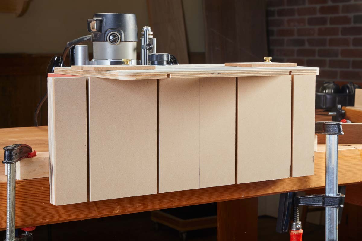
Making Tracks
Aluminum T-track isn’t in everyone’s budget. There’s another way to get the same benefits by making your own tracks. This jig face is made in two layers. The back layer is plywood. Cut a series of dadoes and grooves to suit whatever layout you prefer.
The width and depth of the dadoes should allow the head of a 5/16" hex bolt to slide easily. Next, glue a hardboard layer over the top. Trim it flush, then cut narrower dadoes and grooves centered on the now-buried ones. What you have are custom T-tracks that can accept all manner of stops, supports, and hold-downs.
 |
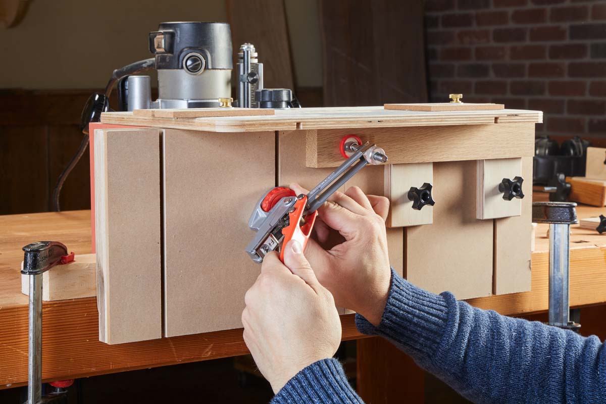 |
| A two-layer face allows you to create T-tracks in any pattern you wish. Don’t forget the centerline. | Clamps and stops can be positioned anywhere to provide registration and a solid grip on a workpiece. |


