


If your workbench is the most-used tool in the shop, the bench vise may be the second most used. Having a vise that you can adjust quickly and offers ample holding power is worth its weight in gold. And, if you made the vise in your shop?
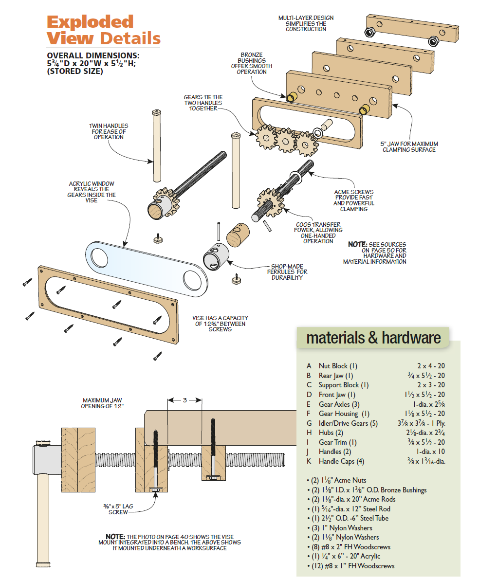
Well, that is where we award extra credit. This vise is of a twin-screw design. Turning one handle causes both to rotate, moving the vise jaw in or out equally on both sides. That’s due to the series of gears visible through the “skeleton” (clear) front. The wood gears connect the handles and give a great, tactile feel as you adjust the jaw.
Now, don’t let the look of this vise scare you. While it may look like a Swiss-made watch, you don’t need to be an engineer to build it. A little bit of woodworking, a little bit of metalworking, and some precise measurements will help bring this all together over a long weekend. Once you’ve mounted it to your bench and put it to work, you’ll be glad you invested the time in this great shop project.
 Three plywood gears connect to cogs on the shaft of the handles. This mechanical train allows you to operate the vise using either handle, quickly and efficiently.
A Set Of Sturdy Jaws
 The vise starts with a set of jaws. If you’re mounting the vise to a newly constructed bench, the rear jaw can be skipped in favor of recessing the nuts into the apron of your bench. For this project however, we’ll build the vise as an auxiliary vise — one that you can bolt on to an existing bench.
To simplify the construction, the rear jaw is built from multiple layers. For the faces of the vise, any hardwood would work. For ours, we used beech as it’s a stable wood and machines nicely.
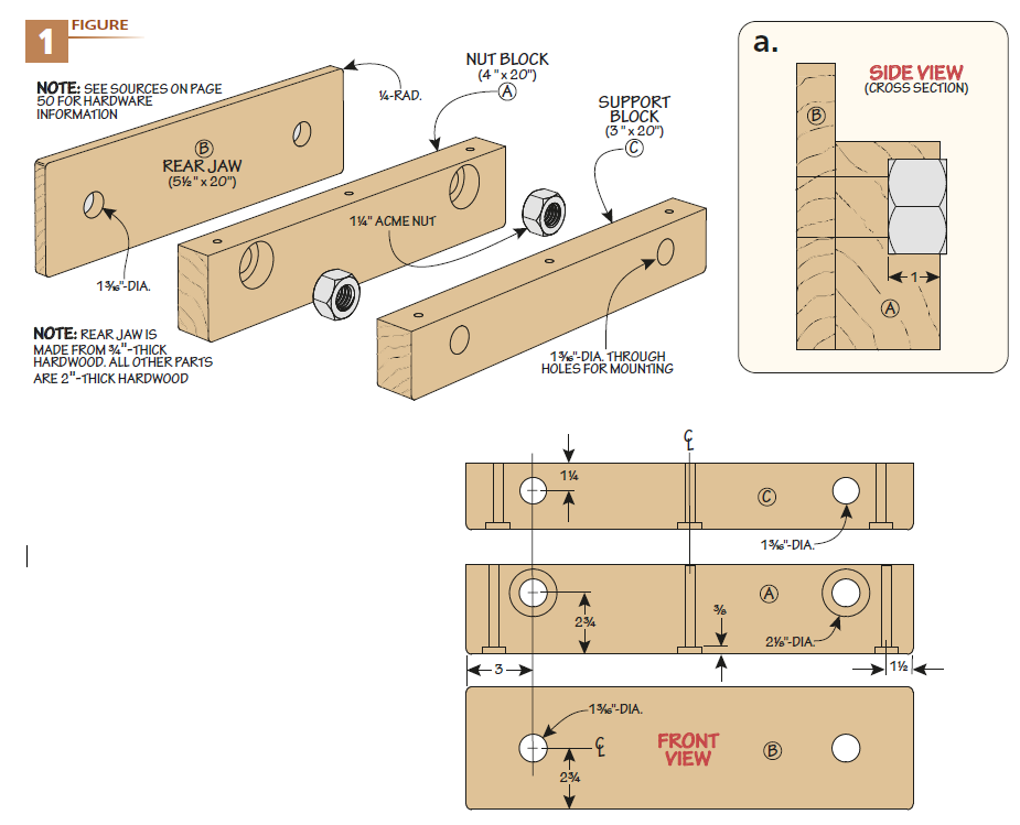
As you can see in Figures 1 and 1a, there are two layers to the vise jaw. After the vise is mounted, a support block is added under the top of the bench to add extra support to the screws. Creating the two-layer jaw is up first.
CONCENTRIC HOLES.
The parts of the rear jaw assembly are a story of concentric holes — holes in the rear jaw need to line up perfectly with the holes for the nuts in the nut block. If they don’t, the lead screws will bind. Likewise, the holes in the support block need to line up with the nut block as well. A little planning and order of operations when drilling these holes is key to making sure everything lines up. After cutting the parts of the jaw assembly to size, head over to the drill press.
Take a moment to mark the bottom edge of the parts — this is the common face that will be used against the fence.Start by drilling the larger counterbore for the nuts in the nut block. A Forstner bit works well here.
You can see the depth of the counterbore in Figure 1a. Once the counterbores are finished, drill the through holes in both the jaw and nut block. Use a set of stop blocks on the drill press fence to keep the holes positioned correctly between the parts. Use a backer board on both parts to help avoid chipping out the opposite face.
The support block is created in much the same way as the jaw face. There are only a pair of through holes drilled in it for the screws to pass through. Note that the location of the holes changes slightly — use the details above to set the fence instead of referencing the bottom edge of the part.
MOUNTING HOLES.
With the screw holes complete, now you can drill counterbores and through holes from the bottom face. These holes allow you to mount the nut and support blocks to the bottom face of the workbench. Glue the rear jaw to the nut block. Wait to epoxy the nut into the nut block until after making the front jaw. It’s critical to make sure the bushing and nuts line up, so use the front jaw with the acme rod to align everything.
FRONT JAW
 The front jaw of the vise is fairly simple. It consists of a jaw block and gear housing. You can see both of these in Figure 2. The housing is there to make room for the gears that you’ll add later.
THE FRONT JAW.
The block, as you see below, is cut to size and contains a series of five holes. The two outside holes are larger and sized for bronze bushings. The bushings are epoxied in place and allows the Acme rod to spin with low friction. The three center holes are for the axles that will allow the gears to link the handles. The axles are cut to length and glued into the front jaw. Make sure that the axles are flush with the inside of the jaw. Set this aside to dry as you turn to the gear housing.
AN OVAL WINDOW.
As you can see in Figure 2 and the details below, the gear housing is a rectangular piece that matches the size of the front jaw. Instead of being solid however, it has the center cut out. This window allows it to form a pocket when it’s glued onto the jaw. (The pocket will be for the gears, but more on that in a little bit). A note before you begin — make this part 1/2" thicker than needed.
In a little bit, you’ll need to make a cover for the gears. The cover will have the same opening as this one, and you can save time by making this part thicker. Forming the large opening can be done in several ways. If you happen to have a hole saw (or wing cutter) of the proper diameter, defi ne the two ends then cut the waste away with a jig saw.
My preference is to create a template out of thinner material and use a router to remove the waste. The thinner material is easier to get to exactly the shape you’d like, and a bearing guided bit will help cut the parts out exactly as you intend. Resawing the housing now will produce both the cover for when you need it, a little bit later. Glue the housing onto the front jaw.
Twin-Screw Skeleton Gear
 The inner workings of this vise remind me of a skeleton watch — one where the movement is visible through the back. As fascinating as it is to observe, it works just as well. Looking at Figure 3 above, you can see that there are a few things to contend with. Let’s start with the gears.
PLYWOOD GEARS.
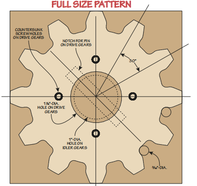
The five gears can be broken into two groups — drive and idler gears. The drive gears are attached to the hubs that are connected to the Acme threads (more on those in a bit). The idler gears pivot on the fixed axles you glued in the front jaw. The teeth configuration on all of the gears are the same — the center hole is the only difference. The center hole of the drive gear is larger and is notched for a pin (see template on the next page).
Prep several blanks by gluing up the plywood and attaching the template from the next page. You’ll need three idler blanks and two drive blanks. Predrill the appropriate sized hole in the center of each. Now, spend some time at the drill press drilling the inside of each tooth.
The “valley” of each tooth is defined with a drill bit to give a clean, crisp profile. Next, you can shape each tooth. A fine-toothed blade at the bandsaw will work if you’re careful and follow the template. In my opinion, a better option, if you have one, is a scroll saw.
Pull up a chair, sit down and carefully cut away the waste on all of the gears. The top of each tooth is flat, while the teeth themselves are double-beveled (flaring out, then in). Don’t forget to notch the drive gear center hole while you’re cutting them out. Of course, if you have a CNC, you could quickly let it cut the gears out as you sip on your coffee.
ACME RODS & HUBS.
With the gears taken care of, it’s time to concentrate on the Acme rods and hubs. The Acme rods are cut to length using a hacksaw. Now, they’re big so take your time and go slow. If necessary, break out the angle grinder with a cutoff wheel. The handle end of the Acme rod has a wood hub clad in steel.
Turn the hub at the lathe. Start by rounding out a blank so that your steel pipe slips over the wood. Then, hold the wood hub in a scroll chuck and bore out the hole using a Jacob’s chuck in the tailstock. You can see the depth of the hole in Figure 3b. When both hubs are complete, epoxy the steel in place over the wood. There are two holes that are needed in the hubs. The first is a pin to lock the hub to the Acme rod.
The second is a hole for the handle. Hold the hub in a V-block at the drill press. With the Acme rod epoxied in place, drill a hole through the steel hub, through the wood, and through the Acme rod. The hub and rod are held together with a steel pin, passed through the hole and epoxied in place.
If you’re feeling wild and crazy, you can countersink the holes and peen the pin. The handle hole is larger, and requires a little more thought. Start by drilling a smaller pilot hole through the hub. Next, use a step bit from both sides to bring the steel hole up to final diameter. Then, you can switch over to a Forstner bit to carefully finish up the hole.
MOUNT THE GEARS.
The drive gear gets mounted to the Acme rod. First, drill a hole in the Acme rod for a pin (see Figure 3a on the previous page. Slip the gear in place against the hub and attach it with screws.
Now, you can really bring the vise together. Slip the idler gears over the axles, applying a little bit of wax for lubrication. Then, place the Acme rods into place, clocking the handles into a position you’d like — you can align them or clock them at 90° to each other. Now, there are only a few more parts to make.
WINDOW & HANDLES
 If you took my advice when you made the gear housing and sliced the trim ring from it, you’ll have it almost complete. All you’ll need to do is rout a rabbet around the inside for a piece of acrylic.
The acrylic can be cut to fit in the rabbet, and two holes for the handle hubs are cut into the front (Figure 4b). The trim ring and acrylic are installed over the gears using a series of screws. Finally, install a set of handles through the hubs — these are simply dowels cut to length (if you made your vise from fancy wood, you can turn your handles to match). Small handle caps are screwed on the end to stop the handles from sliding out. Once the handles are in place, the vise is ready to be installed on your bench.


