


The tool storage you need for the type of woodworking you do is a personal thing. It takes time to figure out what warms your soul and makes you want to spend time in the shop. That’s when you’ll know you’ve arrived in your woodworking journey and want to graduate from the mishmash of cabinets that house your tools (old kitchen cabinets can only be modified so far).
OPTIONS.
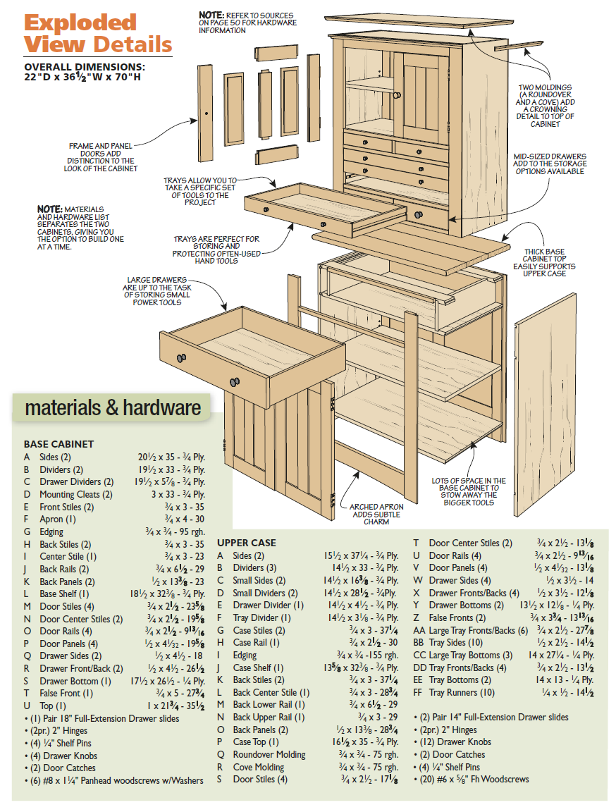
This is a two-part cherry cabinet that sports frame and panel joinery for the doors which enclose storage spaces that will meet all your needs. As you see in the photos here there is an array of drawers and trays that allow you to choreograph not only the storage of fine tools, but the ability to take them on the road to the workbench, or project at hand.
 Drawers with slides handle the heavy stuff that you don’t want banging around. Trays that ride on shop-made runners provide space for smaller, more often used tools.
start with a Solid Base
 The base of the tool cabinet provides storage for the larger tools in your arsenal. As you see in the Figure 1 above there’s a large opening where an adjustable shelf will reside behind a set of doors you’ll make in a little while. The cavity above that space will hold the tool cabinet’s largest drawer. The building process starts at the table saw. The bones of the base cabinet are all plywood parts. After you’ve wrestled the big sheets into the more manageable sizes of the sides and dividers, it’s time to change out the blade for a dado set.
DADOES.
The sides of the base have three dadoes. The lowest dado (detail ‘a’) holds the divider that is the bottom of base. The upper two that you see above in the Side View are next in line. The one in the middle is for the divider that’s the bottom of the drawer cavity. The upper dado is for the mounting cleats you’ll use to attach the top. There are a couple of dadoes left to do in the upper divider for the drawer dividers — detail ‘b’ shows their location. Also, drill the holes for the shelf pins, they’re shown in the Side View.
BASE ANATOMY.
We’re at the point where we can glue up the base, so there’s something I need to bring to your attention — how the front and back assemblies join to the base. If you take a gander at detail ‘c’ and the Side View, you’ll notice that the narrower dividers are centered on the sides. This is to accommodate the rabbets that you’ll cut into the stiles on the front and back assemblies.
This joinery lets the front and back nestle into the body of the case, providing more glue surface.The wide stiles — especially on the front assembly, provide extra rigidity to the overall structure. On the inside edge they’re glued to the drawer dividers, creating the opening for the drawer, and a wee bit more rigidity for the base.
DEALERS CHOICE.
So to address this challenge and make sure that the dividers are centered on the sides during glueup, you can do one of two things. You can cut some 1⁄2" shims to act as spacers when clamping up the base. Or, you can make the stiles and use them as fillers for the glueup. Either way, when you glue up the base, it’s critical that the dividers are centered in the sides.
FRONT & BACK
 Moving on to the parts that will close up the case, I started with the front. As you see in Figure 2, the front is made of two stiles that are joined at the bottom with an apron. Along the top they rest next to some edging that’s glued to the divider and the mounting cleat. Start by cutting all the parts to size.
MORTISES.
Details ‘c’ and ‘d’ show the location of the mortises in the front stiles. If you have a mortising machine go for it. Otherwise get out your Forstner bit and chisel, head over to the drill press, and show us what you can do. Then cut the rabbets along the edge like you see in detail ‘e.’ The apron is next in line. Start off by cutting the tenons to join to the stiles (detail ‘d’). Then shape the arc along the bottom edge (Figure 2d).
For the sake of proper spacing I cut the top piece of edging to size and included it in the glueup of the front frame assembly (do that now). But don’t rely on that union — it won’t stand the test of time. It will last long enough to glue the front frame to the base, which is what you can do when the frame is dry. Apply glue to the rabbets of the stiles and the back side of the top edging, then clamp it to the case. Also add the edging that’s glued to the divider. Now you can make the back.
FRAME & PANEL.
The back is a frame and panel assembly that gives you the visual option of placing it anywhere in the shop and looking good from all sides. Cut the centered grooves in the stiles and rails (Figures 2a and 2b). Then cut the tongues in the center stile and rails. (Don’t forget those rabbets on the edge of the stiles.)
PANELS.
The panels are glued-up hardwood rabbeted along the inside edge. Notice in Figure 2b that the vertical rabbets are wider than the horizontal versions. Later we’ll visit about why the rabbets on the panels are different widths. When gluing up the back, use just a dab of glue in the center of the panels, and only the outside halves of the rails. When the back assembly is dry, you can glue it to the base.
trim it out with Simple Style
 Now it’s time to sub-divide and tidy up the big space that’s the base cabinet. As you see in the figures, this is all about adding a pair of doors, a big drawer, and a thicker than normal top that’s an appropriate crown for the base. Let’s kick off by making the shelf that lives inside the base. The front is edged with the same edging material that you used on the base front. That was easy, now let’s move on to the doors.
FRAME & PANEL DOORS.
If you take a gander at all the visual info above in Figure 3d, you’ll see the joinery details for the two doors. The joinery of doors, (like the back panels on the base) make for a strong, and appealing accent to the surface of the cabinet. The shadowline created by the recessed panels that are held in the stiles and rails break up the surface in an interesting way. The process starts at the table saw by making centered grooves in the stiles and rails.
TENONS.
The next task is cutting the tenons on the ends of the center stile and the rails. You can see both tenons in Figure 3d. After installing a dado blade in your table saw, it’s just a matter of attaching a sacrificial fence to your miter gauge and using your rip fence as a stop to cut the shoulders of the tenons. Then nibble away the cheek waste by backing the workpiece away from the rip fence.
Cutting the rabbets on the panels are the last detail to be done before gluing up the doors. They are the same configuration as the rabbets you cut on the back panels earlier. When they’re cut, you can clean off the appropriate worksurface and gather up the clamps and supplies to glue the doors together.
DOOR DETAILS.
After the glue has done its work on the doors, you can focus on the details required for integrating them into the base. This starts with attaching the hinges — first to the doors (Figure 3b), then to the base cabinet. Drilling holes for the knobs is next up. Figures 3 and 3a provides the information needed. Attaching the magnetic catch and installing the mounting block on the underside of the drawer divider is the last thing to do in this phase, Figure 3c gives you insight on what to do.
A BIG DRAWER
 Now you can turn your attention to the opening in the upper portion of base cabinet where a big drawer lives.
This is the biggest drawer in the cabinet and it’s meant to hold heavy stuff — if you choose to store it there. This is why we decided to attach these to the base with full-extension drawer slides, the heavy-duty kind of slides that can take a beating. Since the slides are going to be doing most of the heavy lifting, we chose a simple, yet sturdy joint to use on the drawer box.
TONGUE & DADO.
Figure 4a and 4c shows the joinery employed for the drawer box. After cutting all the parts to final size, you’ll start the joinery process on the sides. The sides require a narrow dado cut in the ends to mate with the front and back drawer parts.
What follows this is making the rabbet on the ends of the front and back pieces (they are shown in the same details as the tongues). Lastly, before gluing up the box, cut the groove along the bottom edge of all four drawer pieces for the drawer bottom, Figures 4b and 4d shows where it’s located.
FALSE FRONT.
It’s time to install the false front. The easiest way to do this is to first install the drawer slides in the case and on the sides of the drawer box. Figure 4d shows where the set we used attaches to the cabinet and the drawer. You’ll need to confirm the location specifications of the hardware you have on hand. Once the slides are in place on the cabinet and the side of the drawer box, you can slide the box in the opening (with double-sided tape affixed to the box front).
Now it’s time to center the false front in the opening, Figure 4c shows the reveal you’re looking for. When you’re comfortable with the spacing, press the false front firmly against the box. Now you can remove the drawer and screw the false front to the box from inside. Adding the knobs is the last bit of work to do on the drawer (Figures 4 and 4b).
THE TOP.
 Making the top is the last order of business for the cabinet base. As you see in Figure 5, the top is thicker than normal. We felt the top was deserving of a little more prominence so we beefed it up to 1"-thick material. It’s attached to the base with screws through oversized holes.up above there’s a Sturdy Case
While the base cabinet is cooling off in the corner, you can turn your attention to what’s going to live on top — the upper case that you see flowing across. It starts out fairly similar to its older, larger sibling with the plywood construction you see above. But to provide storage for the variety of smaller tools you’ve gathered over time, the infrastructure is quite different. You see at the bottom center of the case there’s an opening for a pair of drawers that are slightly smaller than the one in the base.
This is a perfect space for your mid-sized gadgets. Just above these two are five trays that will let you dial in your access to your fine hand tool cache. Above the trays you’ll have more open space for middling size items. Let’s jump into the case parts.
PLYWOOD PARTS.
 Figure 6 above shows all the parts required for the body of the case. Once you’ve ripped and cut them to their fi nal sizes, we’ll tackle the dadoes where they’re required. All the dado locations are shown in the drawings.
The case sides get three for the dividers that form both the case itself and the case within the case. In esoteric woodworking circles this configuration is referred to as the “Russian doll construct,” just so you know. It will either impress your friends, get you thrown out of your own shop, or leave you with being the buyer at the next happy hour.
The next set of dadoes are cut into the inside faces of the bottom and middle dividers, Figures 6 and 6a show these. There are centered dadoes that need to be cut in the small dividers, Figures 6b and 6c show them in detail. Now that all the dadoes are done, you can focus on the mating tongues. All of them are on the ends of the dividers of both cases.
Drilling the shelf pin holes are a detail that’s more easily done before the case is glued up — so do that. Speaking of keeping things easy, we’ll tackle the glueup of the case in a couple of stages.
TWO-STAGE GLUEUP.
For me, keeping things simple means gluing up the nested section of the case first (the section that holds the drawers and trays) then the case sides and top divider. As a reminder, this case, like the base before, has dividers that are narrower than the case sides to allow for the rabbeted front and back assemblies.
So all the parts involved in the first glueup are flush to each other. It’s when you bring in the wider case sides that you’ll need to consider using shims to center the top divider and the glued up drawer/tray assembly. Then it’s on to making the front and back of the case.
FRONT & BACK
The front and back of the case are similar to the ones that adorn the base, but not exactly alike. On the front, the location of the joined rail is at the top, whereas the apron is on the bottom of the base. And the back rails on this case are two different sizes, not uniform widths like the base back. That being noted, cut all the parts for the front to size.
MORTISE & RABBETS.
 The marching orders are the same for the mortise in the top of the stiles. After drilling the holes at the drill press, square them up with a chisel (Figure 7c and 7d).
Next, it’s a trip to the table saw to rabbet the edges as shown in Figure 7c. Then change the setup at the saw and cut the tenons on the rail (Figure 7c and 7d). Gluing up the front presents the same challenges as before. You can temporarily clamp the bottom edging piece in place while the glue dries.
THE BACK.
 The back is a rinse and repeat of the previous panels. Cut the grooves in the stiles and rails, then rabbet the stiles. Cut the tenons on the center stile and the rails. Then cut the rabbets on the panels (Figure 7a and 7b). Glue up the back now, but don’t install it until the tray runners are in place.
populate the case with Doors & Drawers
To complete this fine project it’s déjà vu all over again. You’ve got doors, drawers, and a top to contend with. The top this time is plywood wrapped with two moldings to give the case a counterpoint to the arc in the bottom of the base. The top is the last bit of work glued to the case: I chose to start there.
THE TOP.
 After spending a few moments at the table saw you’ll have the plywood blank needed for the top. The top is wrapped with a piece of molding you can make with a 1⁄2" roundover bit (Figure 8a). It’s easily made on a length of hardwood at the router table, then mitered and glued to the plywood blank. Underneath the top we’ve added a simple cove molding (Figure 8a and 8c). This is a piece of molding that you can buy if you like, or make it. The top is glued in place on the case.
MORE DOORS.
The doors on the case are smaller than the ones you made for the base, but beyond that, they’re structurally the same. I would like to visit a moment about an element of the doors I haven’t touched on to this point — the rabbeted panels. Since you’ve already made these panels and see how they fit in the frames this might not be news to you, but there are reasons behind the fact that the rabbets are two different widths. First, the narrow rabbets on the sides (Figure 8b) allow for seasonal movement of the hardwood panel.
Second, the wider rabbets on the top and bottom makes for an interesting look on the inside of the cabinets. There’s no reason not make the whole project look good inside and out. So now you can proceed to making the doors and attaching them to the case in the same way you did on the base. Notice in Figure 8c that the mounting block for the magnetic catch is larger to accommodate the wider rail.
THE DRAWERS.
The drawers here are modest in size compared to the one in the base. But they’re just as sturdy and well-connected to the case. The full extension drawer slides used here are a little shorter, but just as strong (Figures 8 and 8f). Again, read and follow the instructions that come with your slides. As you see in Figures 8d, 8e, and 8f, the joinery for these two drawers is the same as their big brother.
TRAYS
 Here’s where we’ve upped the ante on this tool cabinet. I’m talking about the trays you see in Figure 9. The addition of these five trays expands the use of the tool cabinet beyond merely a place to store tools. As you see in Figure 9, the grooves in their sides ride in and out of the case on hardwood runners that are attached to the inside of the case.
NEW JOINERY.
This detail lets you easily bring any of the trays with tools of your choice to the place you’re working. Pretty slick indeed. Since there’s no hardware to contend with, the joinery used here is ideal for these on-the-go trays — locking rabbets.
Often this joint is only applied on the front of a drawer (Figure 9a), and a tongue and dado is used on the back end. But since the drawer box will be seen in its entirety, we repeated the joint on the back side as well. After cutting all the pieces to size, the journey starts at the table saw with the front pieces.
THE STEPS.
You have to stand the workpiece vertically to make a groove along the end. To do this safely you’ll need a zero-clearance insert and a square backer board to hold the workpiece safely against the fence. Take your time doing this cut on all the ends of the fronts and backs, as this is the toughest part of the process.
Next, you cut the rabbeted tongue on the ends to complete these parts. As for the sides, cut the mating dado in the ends of the boards (Figure 9a). Next up are the grooves for the plywood bottom in all the parts, then the wider grooves in the sides (Figure 9c). After cutting the bottoms to size, glue up the trays.
While they’re drying you can make the runners and install them in the case (Figure 9b). When you’ve slid the last tray in place you’ve got one nice cabinet on your hands.
If this a project you would like to build, you can get the complete step-by-step plans and detailed drawings at WoodsmithPlans.com.


